Copyright © Zhejiang Yidek Technology Co., Ltd. All Rights Reserved. Site Map
- +86-577-85600688
+86-17758121688 - grace@yidek.com
- No. 397 Binhai 21st Road, Xinghai Street, Longwan District, Wenzhou City


Product Model | SVG Capacity (Mvar) | Rated Output Current (A) | Cooling Method |
YDK-SVGH-C2.0/6 | ±2 | 192 | Air Cooled |
YDK-SVGH-C3.0/6 | ±3 | 288 | Air Cooled |
YDK-SVGH-C5.0/6 | ±5 | 480 | Air Cooled |
Product Model | SVG Capacity (Mvar) | Rated Output Current (A) | Cooling Method |
YDK-SVGH-C2.0/10 | ±2 | 115 | Air Cooled |
YDK-SVGH-C3.0/10 | ±3 | 173 | Air Cooled |
YDK-SVGH-C5.0/10 | ±5 | 288 | Air Cooled |
YDK-SVGH-C8.0/10 | ±8 | 480 | Air Cooled |
YDK-SVGH-C10/10 | ±10 | 576 | Air Cooled |
YDK-SVGH-C15/10 | ±15 | 864 | Air Cooled |
YDK-SVGH-C20/10 | ±20 | 1154 | Water Cooled |
YDK-SVGH-C30/10 | ±30 | 1735 | Water Cooled |
Product Model | SVG Capacity (Mvar) | Rated Output Current (A) | Cooling Method |
YDK-SVGH-C8.0/35 | ±8 | 132 | Air Cooled |
YDK-SVGH-C16/35 | ±16 | 264 | Air Cooled |
YDK-SVGH-C30/35 | ±30 | 495 | Water Cooled |
YDK-SVGH-C40/35 | ±40 | 660 | Water Cooled |
YDK-SVGH-C50/35 | ±50 | 825 | Water Cooled |
YDK-SVGH-C75/35 | ±75 | 1237 | Water Cooled |
YDK-SVGH-C100/35 | ±100 | 1650 | Water Cooled |
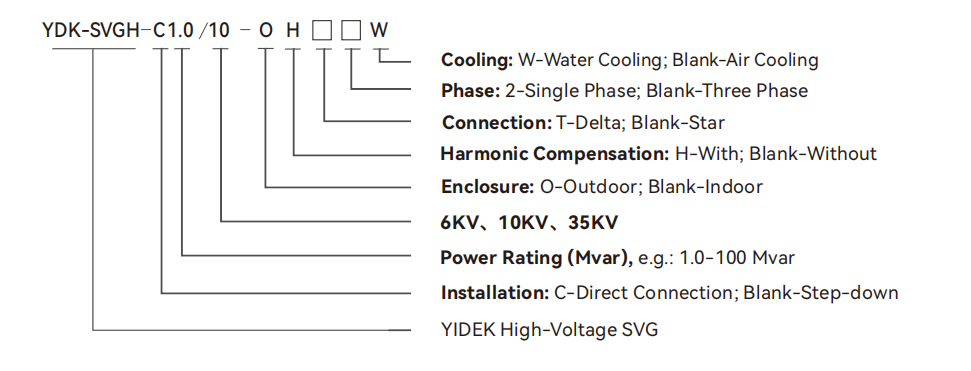
Specification | 3KV/6KV/10KV/35KV |
Rated Capacity | ±1Mvar~±100Mvar |
System Voltage | 3kV、6kV、10KV、35KV |
Frequency | 50Hz |
Functions |
|
Reactive Power Compensation | Power factor correction,continuously adjustable from-1.0 to+1.0 |
Three-Phase Unbalance Compensation | 100%unbalance fully adjustable |
Harmonic Compensation | Up to the 13th order,filtering efficiency>70% |
Functions |
|
Response Time | ≤5ms |
Power Loss | ≤0.8% |
Cooling Method | Intelligent Air Cooling/Water Cooling |
Total Harmonic Current Distortion (THDi) | ≤3% |
Control Power Supply | 380VAC,220VAC,or 220VDC |
Reactive Power Regulation Mode | Automatic, continuous, and smooth adjustment (Capacitive/Inductive) |
Minimum Compensation Power | 5kvar |
Compensation Current Resolution | 0.5A |
Monitoring&Communication |
|
Communication Interfaces | Ethernet,RS485,CAN,High-speed Fiber Optic |
Communication Protocols | MODBUS_RTU,ProfiBUS,Power CDT91,IEC 61850-103/104,CANOPEN,User-defined |
Parallel Operation | Supports multi-unit parallel operation and multi-busbar comprehensive compensation |
EnvironmentalRequirements |
|
Operating Temperature | -10℃~+40℃ |
Altitude | ≤2000m(Special design required for>2000m) |
Relative Humidity | Monthly average ≤90%(at 25℃),non-condensing |
Ingress Protection(IP)Rating | lp40(Indoor),IP44(Outdoor) |