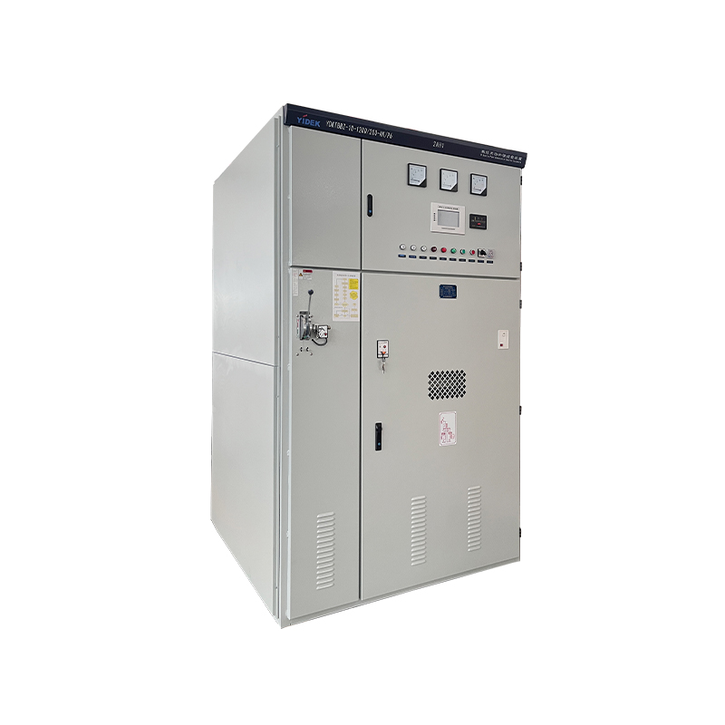
High-Voltage Smart Capacitor Bank
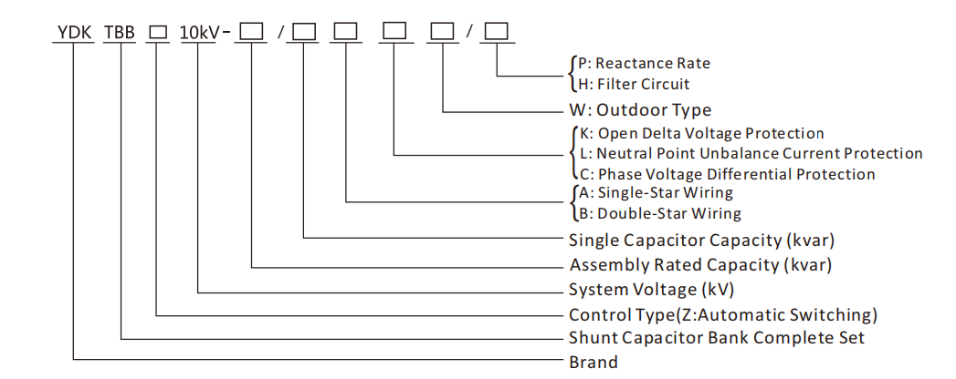
YDKTBBZ
High-Voltage Reactive Power Compensation Complete Set (YDKTBBZ) provides solutions for high-voltage compensation.
YDKTBBZ is suitable for 6~35kV systems, providing solutions for power factor correction, improving voltage quality, and reducing line losses.
YDKTBBZ consists of shunt capacitors, series reactors, zinc oxide arresters, discharge coils, vacuum contactors, disconnector switches, fuses, a power factor controller, and combined main and control circuits.