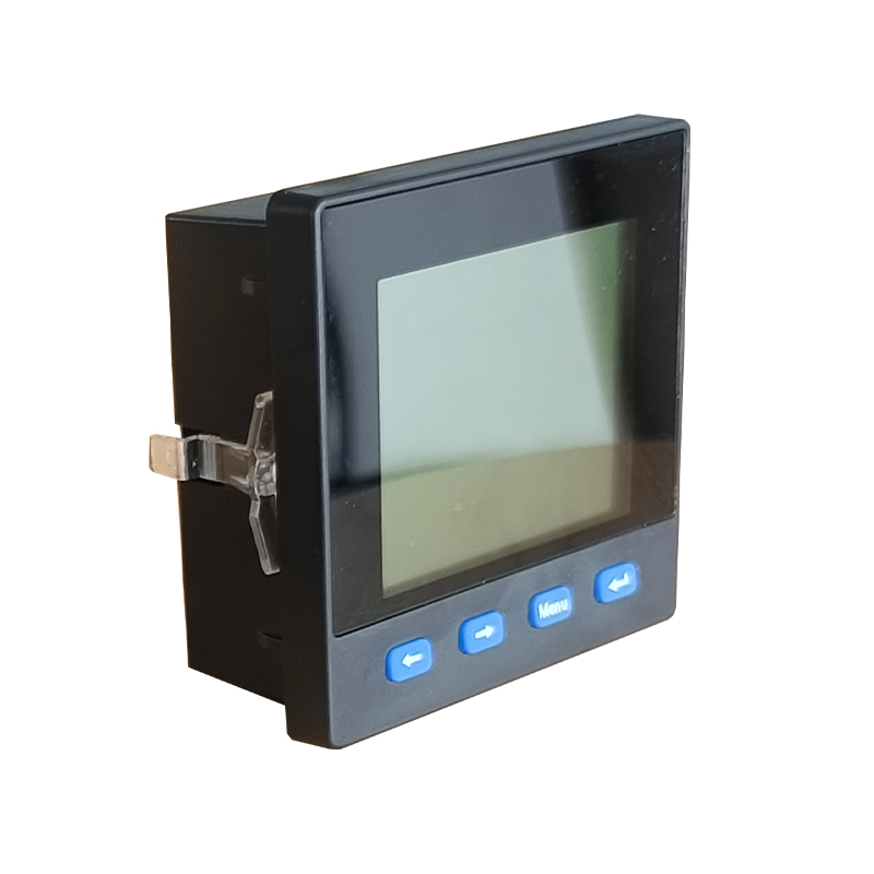
The P354 series single-function power meter can monitor voltage, current, frequency, and has switch status monitoring, over-limit alarm, relay output, analog quantity transmission and communication functions. As an advanced intelligent and digital front-end acquisition component of the power grid, the meter can be used in energy management systems, distribution automation, intelligent buildings and intelligent switch cabinets, it has a variety of wiring methods, is easy to use, and can meet various requirements on site.Model Specifications
Function Model | PZ354-LA1Y | PA354-LA1Y | PZ354-L91Y | PA354-L91Y |
Voltage | √ | , | √ | , |
Current | , | √ | , | √ |
Frequency | √ | √ | √ | √ |
Communication interface | √ | √ | √ | √ |
Switch input | 2 | 2 | 4 | 4 |
Relay output | 2 | 2 | 4 | 4 |
Analog output | 2 | 2 | 2 | 2 |
Measurement
◆ Voltage: phase voltage, line voltage
◆ Current: phase current
◆ Frequency: system frequency
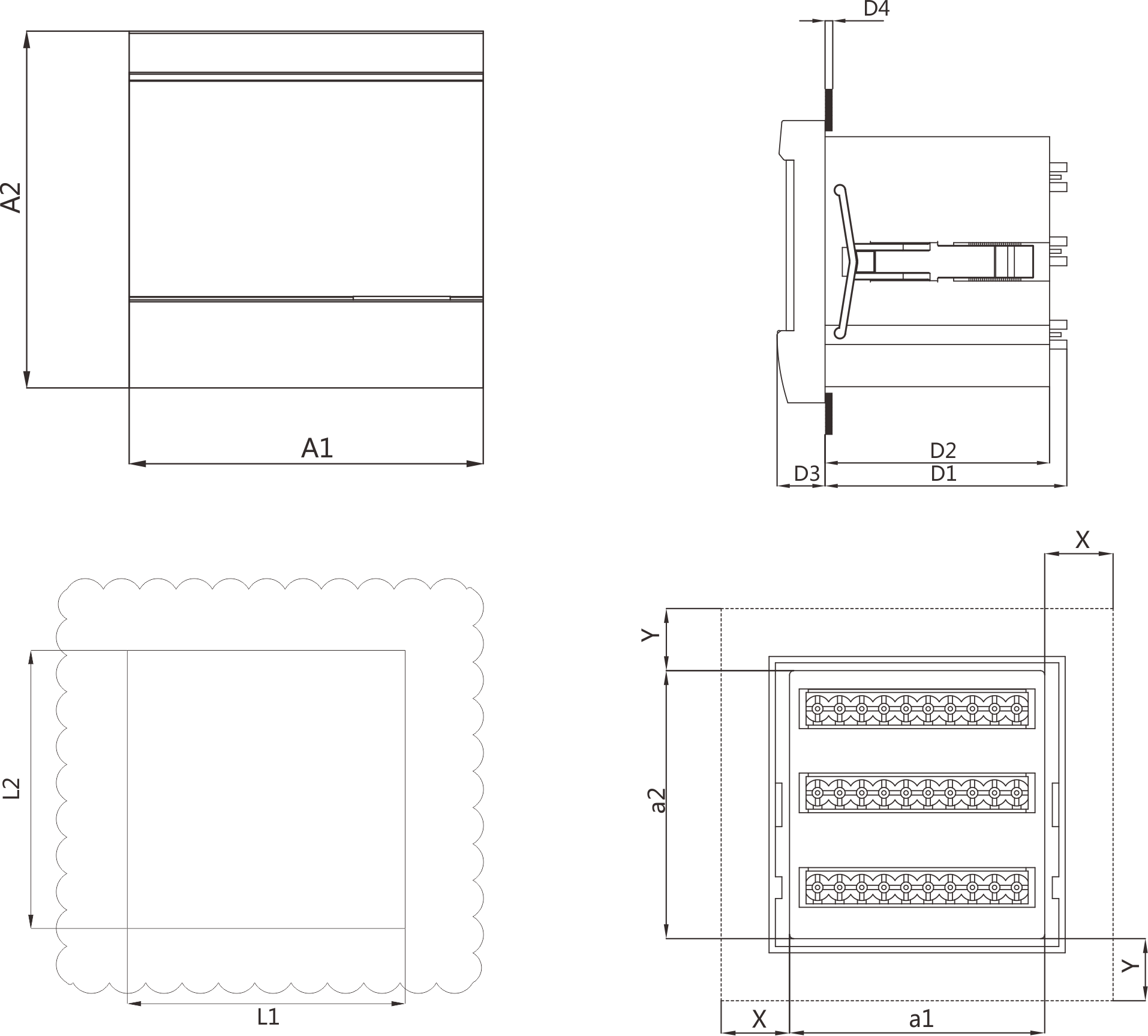
◆ Can directly access 264/456V voltage, higher voltage can use voltage transformer
◆ For ×/1A or ×/5A current transformer, its primary value is programmable
Switch input
PZ354-LA1Y, PA354-LA1Y support up to 2 switch inputs, PZ354-L91Y, PA354-L91Y support up to 4 switch inputs.
Switch input adopts dry contact input mode for monitoring, such as alarm node, opening and closing status, trolley position, capacitor compensation cabinet capacitor input status, etc. The switch input status information can be displayed locally or transmitted remotely through the communication interface.
Relay output
PZ354-LA1Y, PA354-LA1Y support up to 2 relay outputs, PZ354-L91Y, PA354-L91Y support up to 4 relay outputs.
Each relay can set the working mode, pulse width, alarm item, alarm range, hysteresis, and alarm delay in the setting menu, the data format of the alarm range is the secondary grid integer data. The relay working modes are: off, remote control, and alarm.
Off:
The relay output does not act and maintains the default state when the instrument is powered on.
Remote control:
The relay acts or releases by receiving PC or PLC commands through communication. The relay output supports level and pulse mode, and the pulse width can be set to 0.01s~99.99s.
Alarm:
High alarm means that the relay acts when it is higher than the alarm threshold of the alarm item, low alarm means that the relay acts when it is lower than the alarm threshold of the alarm item, the relay is not released until all conditions that trigger the relay alarm disappear, the instrument loses power, or the software shields the alarm function. The relay output supports level and pulse mode, and the pulse width can be set to 0.0s~99.99s, the relay alarm supports alarm delay, and the delay time can be set to 0.00s~99.99s.
Analog output
The instrument has 2 analog outputs, and the analog output items and ranges can be set.
Example 1: Analog output mode: 4~20mA, Analog output item: Ua, Range lower limit: 10.0, Range upper limit: 264.0, That is, 10.0~264.0V of phase A voltage (Ua) corresponds to analog output 4~20mA.
For detailed analog output items, please refer to analog output settings.
Note:
The format of analog output range setting is secondary grid integer data. For specific format, please refer to the table below, the value unit in the analog output comparison table, and the secondary grid data format in the communication address information table.
Analog output mode: OFF, 4~20mA, 0~20mA, 4~12~20mA, 1~5V, etc.
Analog output items: voltage, current, frequency.
Customers need to specify the analog output mode when ordering.
Communication
The instrument has one RS-485 communication interface, using Modbus-RTU protocol. The RS485 communication port should be connected using a shielded twisted pair cable. A bus can connect up to 32 devices, and terminal resistors can be used at the beginning and end of the bus.