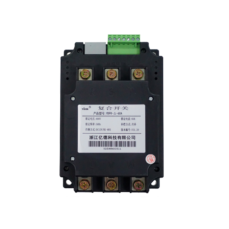
product overviewOur company's composite switch is an ideal product for on/off control of low-voltage power capacitors. It detects external control signals to activate or deactivate capacitors and innovatively adds data communication functions, greatly reducing the complexity of complete wiring.Its main advantages include: automatic search for voltage zero crossing input, search for current zero crossing cutoff, achieving no inrush current switching. Using magnetic holding relays, with low power consumption and no harmonic injection. Equipped with comprehensive self diagnosis and protection functions, it can achieve voltage abnormality protection, phase loss protection, fault self diagnosis, etc. ...Product model and specification description(1)Product model and its meaning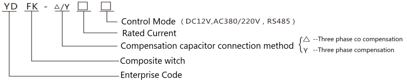
Model Configuration Table
Compensation method | Model | Rated current (A) | Configure capacitor capacity (kvar) |
Three phase co compensation Single phase compensation Compensation method | YDFK-△-100 | 100A | 50 and below |
YDFK-△-60 | 60A | 30 and below |
YDFK-△-45 | 45A | 20 and below |
Three phase co compensation | YDFK-Y-100 | 100A | 50 and below |
YDFK-Y-60 | 60A | 30 and below |
YDFK-Y-45 | 45A | 20 and below |
(2)Technical Parameter
1)Rated working voltage: AC380V/AC220V
2)Control capacitor capacity: three-phase ≤ 50kvar, delta connection method.Single phase ≤ 15kvar, Y-shaped connection method.
3)Rated current: 100A/60A/45A
4)Service life: 2 million cycles.
5)Power consumption: ≤ 1.5W
6)Contact voltage reduction: ≤ 100mV
7)switch withstand voltage: ≥ 2500V
8)Response time: ≤ 100ms
9)Interval between each connection and disconnection: ≥ 1s.
Main technical features
(1) Zero crossing switching
The basic working principle of a composite switch is to achieve voltage zero crossing conduction and current zero crossing cutoff.
(2) Low power consumption
Due to the use of magnetic holding relays, the control device only consumes power at the moment of switching action. And because the contact resistance of the magnetic holding relay is small, it does not generate heat, so there is no need to add heat sinks or fans, reducing losses. It does not cause harm to other electrical appliances running on the same machine, truly achieving the goal of energy conservation and consumption reduction.
(3) By using a microcontroller to control switching and intelligently monitoring the operation status of relays, input power, and loads, it has complete protection functions:
Power voltage phase loss protection: When the system voltage is supplied, the switch refuses to close.
Automatic fault diagnosis and protection: The system automatically monitors the operating status of the magnetic holding relay. If a fault occurs, the switch refuses to close, and after being connected, the fault will automatically open.
No load protection: When no load is connected, the switch refuses to close.
Power outage protection: In the event of a sudden power outage after closing, the switch will automatically trip and disconnect.
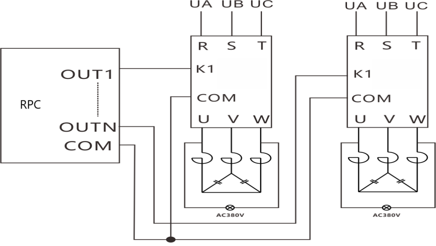
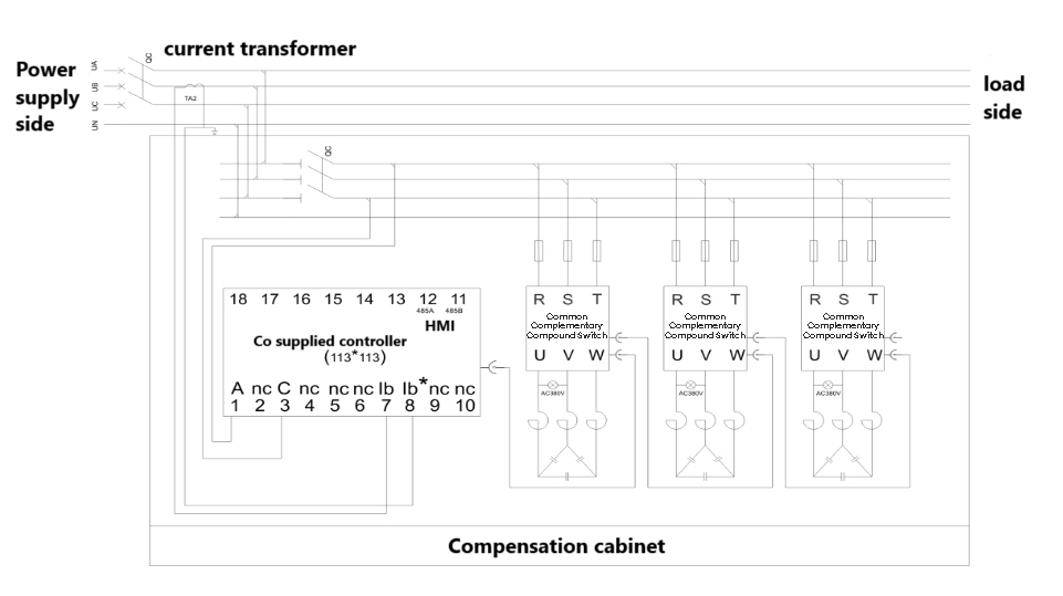
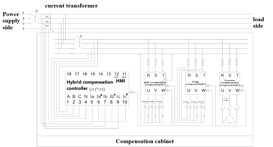
(4) The input signal is optically isolated from the capacitor switching switch and equipped with 485 communication control. It can be used interchangeably with conventional controllers and can also be used in conjunction with our company's controller (485 communication). And it adopts 485 communication control, with simple wiring and easy installation and debugging for users.
(5) Strong anti-interference ability, safe and reliable work.
Precautions before use
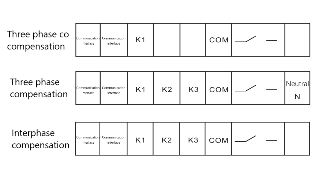
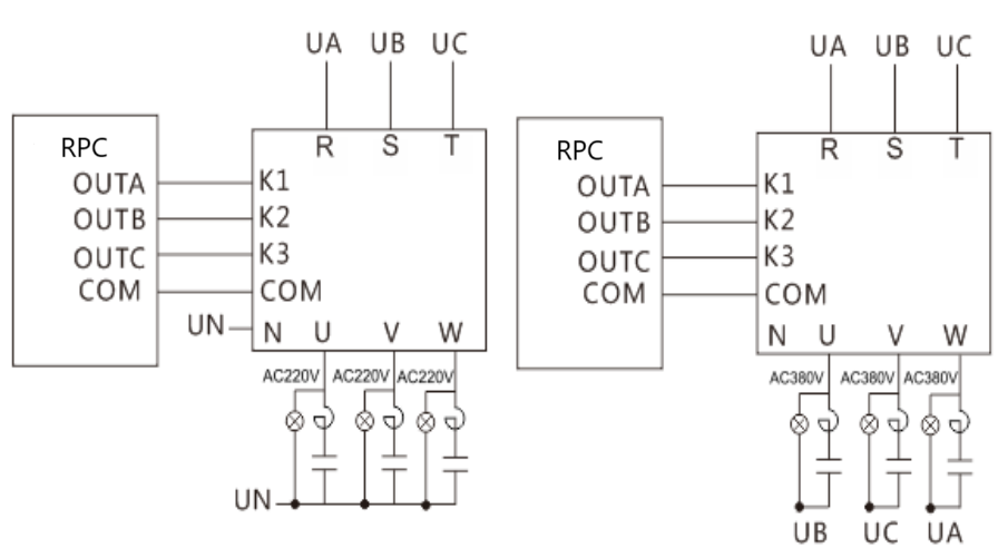
(1)Connection
1)Communication input and output must not be reversed.
2)DC control mode: The polarity of the input level signal should be connected correctly.
3)Communication control method: Please confirm the control voltage.
4)485 communication control method: The data cable is correctly and properly plugged in.
5)Attention must be paid to matching the capacity of the switch with the connected capacitor appropriately.
6)The three-phase phase sequence of the main power circuit A, B, and C must be connected correctly.
(2)Indicator light display
No. | Pilot Lamp | Light | Flicker | Extinguish |
1 | Three phase co compensation | A | Investment | Power on self-test delay Capacitor discharge delay | Can be invested |
Three phase compensation | A、B、C |
2 | Power Supply | Normal | —— | Not powered on |
3 | Communication | —— | Communication is normal | Communication abnormality |
4 | Connect | Networking successful | —— | Not networked |
5 | Fault | Fault | —— | Normal |
Note:
(1)The fourth light on the left is a reserved light and does not light up.
(2)The flashing of A (B, C) during startup is a self-test.
Operation method
(1)Power on self-test function
1)Automatically detect the status of the capacitor switch when turned on, and automatically restore normal working conditions.
2)The constant or flashing power light indicates the normal working state of the composite switch.
A. When the B and C lights are given an external control signal, they will light up correspondingly, and only the A light will light up in total.
When the composite switch self-test error occurs, the fault light will turn on a red light.