(1)Measurement accuracy:Voltage: ≤± 1% (within the range of 80% to 120% rated voltage).Current: ≤± 1.0% (within the range of 10% to 100% rated current).Power factor: ≤ ±1.5%.Reactive power: ≤ ±2%.Temperature: ≤ 1℃.Sensitivity: ≤ 200mA.(2)Output mode: RS485 communication, controlling our company's composite switch.(3) Power supply conditions:Working voltage: AC 220V (separately supplemented) or 380V (jointly supplemented).Voltage deviation: ± 20%.Sampling current: ≤ 5A.Power consumption:<. 5W.Rated frequency: 50Hz ± 5%.Input impedance: ≤ 0.2Ω.(4)Number of networked units: JKW-RS co compensation controller can be connected to ≤ 30 co compensation composite switches. JKW-RS hybrid compensation controller can connect up to 10 sub compensation composite switches, with a total number (total compensation+sub compensation) of up to 30 units.(5)Execution standards: JB/T9663.Mixed parameter names and content description (Table 1)Number | Parameter Name | Display Content (Example) | Annotation |
1 | PFA | 0.988 | A-phase power factor |
PFB | 0.988 | B-phase power factor |
PFC | 0.988 | C-phase power factor |
2 | UA | 220.0 | A-phase voltage (V) |
UB | 220.0 | B-phase voltage (V) |
UC | 220.0 | C-phase voltage (V) |
3 | IA | 3.000 | Secondary current of phase A incoming line (A) |
IB | 3.000 | B-phase incoming line secondary current (A) |
IC | 3.000 | Secondary current of C-phase incoming line (A) |
4 | QA | 1.72 | A-phase reactive power deficit kvar |
QB | 1.72 | B-phase reactive power deficit kvar |
QC | 1.72 | C-phase reactive power deficit kvar |
Three phase common compensation display parameter name and content description (Table 2)Number | Parameter Name | Display Content (Example) | Annotation |
1 | PF | 0.988 | Three phase average power factor |
2 | UAC | 380.0 | AC phase voltage (V) |
3 | IB | 3.000 | B-phase incoming line secondary current (A) |
4 | QAC | 1.72 | Total reactive power deficit kvar |
Name and Content Description (Table 3)Number | Parameter Name | Display Content (Example) | Annotation |
1 | S-PH | 0.99 | Cut off threshold setting range (0.90~-0.81) |
2 | S-PL | 0.95 | Range of investment threshold setting (0.8-1.0) |
3 | S-UH | Three phase compensation 260.0 Three phase co compensation 450.0 | Overvoltage setting range |
4 | S-UO | Three phase compensation 245.0 Three phase co compensation 425.0 | Supplement: (240V~280V) |
5 | S-UL | Three phase compensation 173 Three phase co compensation 300 | Co supplementation: (400V~480V) |
6 | S-YS | 10 | Warning voltage setting range |
7 | S-IL | 100 | Supplement: (220V~260V) |
8 | S-CT | 1 | Co supplementation: (380V~460V) |
(1)Parameter viewing
After about 6 seconds of startup, PF or PFA will be displayed,In the parameter name interface, press the "Execute" button to scroll through the menu, and press the "Confirm" button to view the menu parameters. In the parameter name interface, press the "confirm" button to return to the parameter name interface.
(2)Parameter setting
1)After booting up, the system will automatically enter the parameter viewing interface. After long pressing the "OK" button for 3-4 seconds, the display interface will show "S-PH", indicating that the parameter setting interface has been entered. If the "Execute" button is continuously pressed, the display interface will flash once, showing S-PH → S-PL → S-UH → S-UO → S-UL → S-YS → S → IL → S-CT. If you press the "confirm" button, the specific setting value will be displayed after it.
2) When a set value needs to be modified, press the "Confirm" button to adjust the flashing character to that value, then press the "Confirm" button to move the flashing bit to the right in sequence. Press the "Execute" button to change the value of the flashing bit from 0 to 9 in increments. After adjusting the value, press the "confirm" button to shift the flashing to the parameter name, and the parameter setting is complete.
3)After the parameter settings are completed, press the "confirm" button for 3-4 seconds to return to the parameter display interface.
Controller and composite switch networking test
The composite switch connected to the controller can achieve automatic networking without setting any parameters. Specific debugging methods:
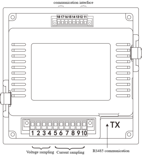
(1)Check the wiring of the controller and composite switch according to the drawings to ensure correct wiring.
(2)After powering on the controller, ensure that the controller displays and collects data correctly. Set the parameters of the controller according to the needs, and ensure that the power factor of the controller is displayed as 1.000 to avoid the use of composite switches.
(3)After all composite switches are powered on, their communication indicator lights flash intermittently, and surface communication is normal. At this point, check whether the number of green LED light groups lit on the controller matches the number of composite switches in the network. If they match, the communication part is completed (usually taking 5 minutes), indicating that the communication network is normal and the debugging is completed. . .
(4)Switching test of composite switch
1) If the test site can provide the current required for the switching of the composite switch, actual switching can be carried out. If the conditions are not met, analog switching (without outputting current) can be used. Simulate switching by long pressing the "Execute" button on the controller for 3-4 seconds to enter or exit the simulated switching mode. After entering the simulated switching mode, the parameter interface will display the first character as "n" (such as "nPF", "nUAC", "nPFA", "nUA", etc.), and the power indicator light will turn green and flash, indicating that it has entered the simulated switching state.
2)Select manual mode through the "Manual/Auto" button on the controller, press the "Confirm" button to sequentially activate the composite switches, and press the "Execute" button to sequentially deactivate the composite switches activated in the network.
Note: Switching from simulated switching mode to normal switching mode allows for direct power-off and restart.
.The communication debugging and simulation switching test are normal, indicating that the entire intelligent reactive power compensation system can be put into operation normally.
Common Fault Analysis
Common situations | Cause analysis and handling methods |
Composite switch cannot be detected | The data cable is not properly plugged in, please recheck the wiring. |
Incorrect current measurement | The controller displays the secondary current of the primary current transformer in the main cabinet, and uses a clamp meter to check if the primary current transformer in the main cabinet has current output. |
PF value and reactive power display negative values or do not match the actual values | (1) A negative display value indicates that the system is in an overcompensation state. (2) If the displayed value does not match the actual value, check whether the phase sequence of the sampled current signal and the sampled voltage signal corresponds one-to-one. |
The system is in an overcompensation state, and the composite switch cannot be activated | Follow these steps to determine the cause: (1) Determine that the power factor is below the input threshold, and the system is under compensated. (2) Ensure that there have been no instances of exceeding limits or malfunctions. (3) Calculate whether the use of a composite switch will cause overcompensation. As the device uses reactive power as the physical quantity for switching, if the use of a composite switch will cause overcompensation in the system, the composite switch will not be used. |
Compensation is normal during the day, but the ideal compensation effect cannot be achieved at night | The reason may be that the local area consumes less electricity at night, and when the composite switch is turned on, it will cause the system to overcompensate, resulting in the compensation not achieving the desired effect. |